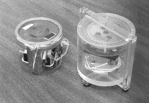
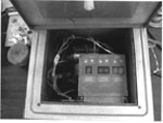
Photo 2: View inside the calorimeter with the new sonofusion reactor and its ocillator electronics. The argon pressure line is not attached and the reator fill tube is open.
[Return to Device Update] [Return to Feature Articles]
Infinite
Energy Device Update
Published
in IE Volume 7, Issue #39, September-October, 2001
Former NERL physicist Jeff Kooistra developed an unusual electric motor, a derivative of one originally conceived by the late Stefan Marinov. The Marinov Motor concept was modified and demonstrated through the efforts of Kooistra, Tom Ligon, and Tom Phipps; this design was called the KLP Motor. (See IE Issues No. 17, pp. 40-48; No. 18, p. 7; No. 19, pp. 57-71, 85; No. 20, pp. 7-8.) The KLP took the magnetic torus-shaped rotor of the Marinov design and made it of two stacks of opposing polarity magnets with leakage flux allowed. It also improved the electrically conducting ring around the magnetic torus by making it a multi-turn coil.
Jeff made a discovery while investigating the ability of the earlier,
solid copper ring to rotate while the permanent magnet structure was fixed in
position, another permutation of the Marinov/KLP concept. When the DC current
was applied to the ring, the direction of rotation of the ring could be reversed
if the electrical brush contacts were made at the inside diameter of the flat,
washer-like shaped ring instead of at the obvious outside diameter. This reversal
made the ring rotate in the same direction as the magnetic structure would rotate
if it were allowed to rotate. Jeff did another experiment to see what would
happen if both structures were allowed to rotate. He found that both the ring
and the magnets rotated in the same direction. This was an astonishing result,
so he called it the "Warlock's Wheel."
NERL recently completed the construction of a prototype KLP Motor. Retired engineer
Jan Roos took Jeff's prototype that had been made within a styrofoam coffee
cup as its frame (the "cup motor," as we called it), which exhibited
prograde, same-direction rotation of the stator when the entire motor was suspended
from a nylon monofilament from the ceiling. Jan transferred as much as he could
of Jeff's coffee cup design to a better-built prototype. Contrary to classical
physics, the cup motor seemed to be exhibiting an apparent violation of Newton's
Third Law of Motion-for every action there is an equal and opposite reaction.
When Jeff's motor would work at all, as its construction was very crude, its
"stator" and attached batteries would rotate in the same direction
as the rotor, prograde motion, an unheard-of behavior for a motor. One of the
times during which it did function, it was recorded on video tape running prograde
and then some retrograde, but clearly not the decided retrograde direction normally
expected. In comparison, a standard, miniature DC motor with a flywheel load
attached to its shaft exhibits its stator and batteries spinning in the opposite,
retrograde direction from the rotor and flywheel, in conformance with Newton's
Third Law. Naturally, we wanted to clearly and unambiguously demonstrate the
KLP Motor's ability to violate this Law, if possible. Jan's prototype showed
retrograde motion of the case upon acceleration, but settled down to no motion
of the stator when the stator was held in a jeweled bearing frame which allowed
the stator to rotate also. We did not see prograde motion of the case to any
extent, though some was seen. Prograde motion is definitely seen when the motor
decelerates. A conventional motor was built with the same construction technique
to see if the torque necessary to keep the internal rotor spinning under steady
speed conditions was less than the stator housing bearings' friction. The conventional
motor had the same behavior: it would exhibit retrograde stator torque upon
startup and then settle down at the same, steady speed to a torque which is
less than the friction of the bearing supporting the rotatable stator in the
frame. See Photo 1. A gyroscope often spins without its housing spinning at
all, so a lack of stator rotation is not a sign of a violation of Newton's Third
Law.
Out of the disappointments of Jan's prototype, we wondered if the behavior of
the KLP Motor and the Warlock's Wheel were conventional after all.
|
| Photo 1: The KLP motor and internal rotor are on the left. The stator contains the 300 turns of 34 gauge magnet wire coils, bundled with rubber bands, and two batteries with switching circuitry, as the KLP motor is an opto-electronically commutated DC motor. Inside the stator housing and on top is the rotor, containing two rectangular magnet staacks; one stack has a black tape marker on it. The conventional motor is on the right, made from a 12VDC fan; the fan blades were cut off and the rotor with the magnets was glued on. The conventional motor is inside the frame and the inside rotatable stator outer jacket, used to hold teh stator and to reduce windage. Its rotor is nearly the same speed as the KLP rotor, when this latter and its stator assembly were inside the rotatable stator outer jacket. |
|
|
Photo 2: View inside the calorimeter with the new sonofusion reactor and its ocillator electronics. The argon pressure line is not attached and the reator fill tube is open. |
|
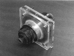
| Photo 3: The original sonofusion piezoelectric assemblies mounted in a reactor made of three acrylic plates. |
|
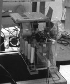
| Photo 4: The Crest oscillator resting on the rim of the calorimiter. The joule heater bank and the circulation fan are visible. |
I had not studied the motor in depth when Jeff was here. So, I
chose to do an analysis of the forces involved myself, using nothing more than
the F = IxB law, and the axiom that parallel flux lines repel and antiparallel
lines attract. I found that the Warlock's Wheel behavior can be entirely explained
by these means. Leakage flux of the unusual magnetic stack is the active magnetic
flux. Jeff also identified a "Lorentzian hook" in the rotating ring,
and I found this piece of evidence to be key. When current is introduced to
a conductive ring with a substantial change in radius, that radial current flow
in the ring near the contact point, in the presence of the magnetic field of
the KLP magnet structure, exhibits a standard IxB force which causes rotation
of the ring. Jeff's big question was how could this rotation exist simultaneously
with a force which causes the magnetic structure to rotate in the same direction?
The answer is that the stationary current leads which touch the conductive ring
via brushes or pools of mercury feel the countertorque of classical electricity
and magnetism. The forward torque was magnetically imparted to the magnetic
structure from the current in the hand-held leads, which then imparted torque
to the ring. The motion of the ring and magnets in the same direction hides
the fact that there are opposed forces between the magnets and the ring, and
at this point, we have no reason to believe that they are not equal forces.
The hand-held leads react against the leakage flux of the magnets, then the
leakage flux of the magnets reacts against the force created in the current
in the ring. This analysis may not be correct, but, by Ocham's Razor that the
simplest explanation is often the best explanation, it fits.
And so goes research. In order for new discoveries to be made, mistakes are
often made along with them. The KLP Motor started as exploration for its own
sake, even before Jeff came to NERL. The Marinov Motor and its KLP descendent
do not exhibit anomalous motor behavior as far as we know. The motor is novel,
in the sense that conventional motor analysis says it would not work. We will
not pursue these concepts any more since they appear to offer no alternative
to the world's present energy sources and do not substantially change the physics
by which we search for new forms of useful energy.
The calorimetry provided by Roger Stringham (see Issues No. 35 and 36) was
totally replaced by one Seebeck envelope calorimeter (SEC). The old calorimetry
was too inaccurate to resolve the excess heat with confidence. Roger's original
reactor completely filled the SEC, so to fit the oscillator electronics inside
the SEC, we redesigned the reactor to be much smaller. See Photo 2.
When the new reactor was tested, calibration was much better, but excess heat
in the experiment was not found again. Numerous changes may be responsible for
the "turn off" and they are still being investigated. The resonant
frequency of the piezo and reactor combination has changed. The Crest 275D oscillator
operates around 38 to 39 kHz, presumably the resonance of the original reactor
provided by Roger. We did not test it, and the original reactor is now in pieces.
The new reactor was found to be 46.3 kHz when filled with heavy water. A mechanical
stop inside the reactor for positioning the piezo transducer assemblies was
removed. That stop was where the titanium "radiating bars" rested,
assumed to be raising the frequency by increased mechanical stiffness. Since
the oscillator was drawing 50 to 70 watts instead of 20 to 30 watts as before,
and the reactor was heating to 100°C without a heater, it is believed that
the stop was also conducting vibrational energy away from the water in addition
to detuning the reactor, which caused it to draw more power. The removal of
the stop decreased the resonant frequency to 45.7 kHz, still far from the 39
kHz drive signal. The original piezos were mounted in a reactor composed of
three plates of acrylic in order to look for proper cavitation and resultant
sonofusion at atmospheric pressure and to measure that resonant frequency, believed
to be close to the original resonance. See Photo 3. No excess heat was found
and the resonance was 43 kHz. We had to cut the oscillator circuit board in
half to make it fit inside the SEC; perhaps this has shifted the drive frequency.
Crest has not yet responded to our inquiry about the factory set frequency.
Another permutation of the calorimetry we are trying is to keep the electronics
outside of the SEC and to directly measure the ultrasonic electrical power going
into the piezoelectric transducers. This is difficult to do accurately, and
is the reason Roger selected a separate calorimeter for the electronics, which
subtracted the heat dissipated from the electrical power drawn from the 120
VAC 60 Hz line source input to the oscillator. The result, by conservation of
energy, is the ultrasonic power delivered to the reactor. Chris Eddy of Pioneer
Microsystems has custom manufactured two single-channel, second generation ultrasonic
watt meters for us. We will report the results of that testing when it has been
completed.
There is a resistor bank and a small DC fan attached to the oscillator inside
the SEC so that the SEC can be calibrated. See Photo 4. The new reactor has
allowed us to insert a teflon plug in place of water between the piezo assemblies
for further calibration, with or without the oscillator inside the SEC. The
plastic plug absorbs vibrational energy as heat and makes for a very good joule
heat calibration via the ultrasonic electrical input. The ultrasonic watt meters
can be very accurately calibrated this way. The calibrated heat release inside
the reactor also provides assurance that spacial location inside the SEC is
not a problem; the fan helps reduce this minor influence even more. Excellent
calibration errors of about 0.1 watt have been obtained with these methods.