[Return to Device
Update] [Return to Feature Articles]
Infinite
Energy Device Update
Published
in IE Volume 7, Issue #40, November-December, 2001
New
Energy Research Laboratory Device and Process Testing Update
Ken Rauen
Solid,
8.5 watts excess heat, 40% over-unity, S/N > 40/1 achieved.
In late 2000, NERL selected one of Roger Stringham's sonofusion
processes as the best method of demonstrating cold fusion via a commercial device.
It has been our intention to replicate the excess heat, and then to clean up
Roger's design for small scale production of the reactor and associated instruments.
In this way we will be able to reliably demonstrate cold fusion on demand to
anyone with minimal experimental skills. We replicated the excess heat with
Roger's reactor and calorimetry, but did not always find excess heat as Roger
had claimed for his setup. Likewise, what we found was a maximum of 30% excess
heat, not the 100% excess heat which he claimed to see with the same device.
We built a version more suitable for sale, but until this time had never found
any excess heat from the new reactor. New ultrasonic wattmeters from Pioneer
Microsystems allowed us to move the ultrasonic oscillator electronics outside
of the Seebeck envelope calorimeter (SEC), so that only the reactor, a circulation
fan, and calibration resistors are inside the SEC. This sequence of events in
our experimental program was covered in detail in previous issues.
Lacking the ability to hire a consultant in piezoelectrics and
ultrasonics, we have had to learn some things on our own. We thought that the
Crest oscillator was operating at the resonance of the piezoelectric ceramic
transducers, but we were wrong. The resonant frequencies we reported in the
last issue were not an indication of a drift of the system's operation. We measured
electrical impedance and plotted it. See Figure 1. The complex impedance of
the piezos is influenced by many factors. Crest uses a 5 mH coil in series with
each piezo, which changes the impedance curve, generally lower in impedance
and with slight shifts in the multiple resonant frequencies. We now do not know
where the system will produce the desired acoustically induced fusion events.
Since the 38 to 39 kHz pulsed sweep used by the Crest electronics is not over
any resonance of the piezos, we do not know what conditions to establish in
a new oscillator. Even Roger does not know what is going on, as he never changed
any parameters in this sonofusion system; it always ran the same way, which
always produced excess heat. His other system designs have produced excess heat,
and greater heat at that, but not repeatably, so this is why he recommended
the Crest oscillator swept system for a commercial demonstration device.
To further understand what has been happening, we reassembled
the original reactor from Roger-finicky seals, connections, and all. It did
not produce any excess heat. We then tried to figure out what had changed. Neither
Roger nor Crest, the manufacturer of the ultrasonic oscillator used by Roger,
knew what had happened.
When we built the new, smaller reactor, we selected titanium
endcaps for the piezoelectric "stacks," the transducer assemblies.
These titanium "radiating bars," as the piezoelectric industry calls
them, are not cemented to a stainless steel water bath, as they are in jewelry
cleaners. The radiating bars are the reaction chamber surfaces which are directly
exposed to the heavy water in our unit. Roger found nearly all of the metals
he tested to have active fusion sites, even when there was no target foil inside
the reaction chamber and all that remained was the metal chamber itself. Titanium
was found to be an active metal and he recommended that we use it for our exposed
piezo stack surface. Normally, aluminum is used for the radiating bars, but
aluminum will be easily damaged by the acoustic energy, just as we saw with
the copper target, reported earlier. The radiating bars must have a low density
in order to transmit the acoustic energy without significant attenuation. Steel
is too dense, so titanium was selected, as it also is resistant to ultrasonic
erosion.
In an effort to narrow down the nuclear reaction pathway, the
new reactor with the titanium in the stacks was first tested with deuterium-depleted
water, 3 ppm deuterium. No excess heat was found, as anticipated. Then the water
was replaced with normal, distilled water; again no excess heat was found. That
water was replaced with heavy water, which is 99.9% deuterium oxide. This time
the excess heat was expected, but again it did not occur. This was reported
in a prior issue. It turns out that titanium forms a stable hydride, derived
from the hydrogen of the water. The protium oxide exposure may have "poisoned"
the titanium against excess heat production. Since the hydride is so stable,
it is not likely to establish an equilibrium reaction with the water to exchange
hydrogen isotopes. The protium in the hydride seems to remain there. We hypothesize
that if deuterium does not get into the metal lattice, fusion does not significantly
occur.
The protium hydrided titanium radiating bars were machined to
expose fresh titanium under the surface. About 0.020 inches were machined off.
No excess heat was found with the exposed titanium. We do not know how deeply
the hydride layer forms, so we may not have removed all of the protium. Much
more cannot be removed, because the thickness is critical to the mechanical
resonance of the stack.
New titanium piezo stacks were installed. Finally, excess heat
appeared-this time in a major way. One test was run for 57 hours, establishing
excess heat long before thermal equilibrium was obtained 11 hours from the start,
reaching 8.5 watts, 41 hours from the start. No "heat after death"
was observed. With approximately 20 acoustic watts of input (estimated to be
around 195 dB sound pressure level), 8.5 watts of excess heat is about 40% over-unity.
At 46 hours into the run, the program was changed to monitor
a resistance heater pulse input to the SEC. The purpose of this test-an on-the-fly
calibration-was to document the scale of the SEC calibration, to make sure that
it had not changed. We put 2.3 watts of regulated DC voltage and current into
the resistor for 3 hours, and a 2.3 watt stepwise rise was seen in the heat
detected by the SEC, verifying that the scaling of the SEC had not drifted.
Next, the ultrasonic oscillator was shut off and the SEC heat was allowed to
drift to thermal equilibrium; this checked the zero of the system calibration,
as the ultrasonic wattmeters were still on. The system drifted to +0.2 watts
of excess heat in 14 hours. See Figures 2 through 6 for a graphic display of
the results.
The excess heat measured was validated. Though we successfully
replicated Roger Stringham's work earlier this year, this robust result feels,
at this writing, much more secure. Our previously stated goal of this replication
effort had been to take this cold fusion system to a commercial product. Finally,
we are close to doing just that. As this issue goes to press, we are building
a second set of hardware. If it also produces excess heat, we will build a total
of ten systems. If most of these produce excess heat, we will go into production
of demonstration devices for sale. We hope that in the next issue of Infinite
Energy we will be able to announce the availability of these long-awaited tangible
proofs, which we have needed so badly. The skeptics said they would only believe
cold fusion is real if they could buy a device at K-Mart. These will not be
sold in K-Mart, but the skeptics will be able to buy them from us instead. Stay
tuned.
We still intend to do a systematic search to identify the "sweet
spot," the exact conditions which cause the fusion of deuterium into helium
in an acoustic field. The Crest oscillator produces a burst of ultrasonic power,
which changes in frequency as it rings down to zero amplitude; we do not know
what the precise conditions of the fusion events are. Our search will be done
with a constant amplitude, 100% duty cycle, sine wave oscillation. Once we identify
exact conditions, it will be possible to excite the water continuously with
ultrasonic energy and produce far more excess heat, which may make this process
viable for steam production to power a turbine and generate electricity.
 |
|
|
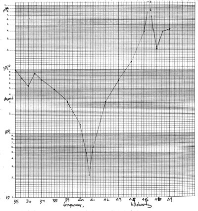
Figure 1. This is a plot of the measured electrical impedance
(ohms) of a titanium mounted piezo stack manufactured by Crest Ultrasonics
with a 5 mH coil in series. The impedance varies from 22 ohms to over
10,000 ohms from 35 kHz to 47 kHz.
|
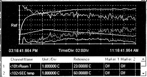
Figure 2.The excess heat run data from the Hewlett-Packard
BenchLink data file is displayed in three overlapping segments. The first
segment is in this figure. We apologize for the imperfect display of the
BenchLink graphics; the HP software and Microsoft Works do not work well
together. Each line on the graph has unique settings for vertical scale
and offset in order to present the data most clearly. The legend below each
graph in Figures 1 through 3 identify the settings for each line; all five
traces are identified, only two identified in each figure. The vertical
scale is in units per division and the vertical offset is the value at the
center line, marked "Ref" for reference. The lines are identified
from top to bottom at the right side as SEC heat, ultrasonic power, excess
heat, room temperature, and SEC temperature. |
 |
 |
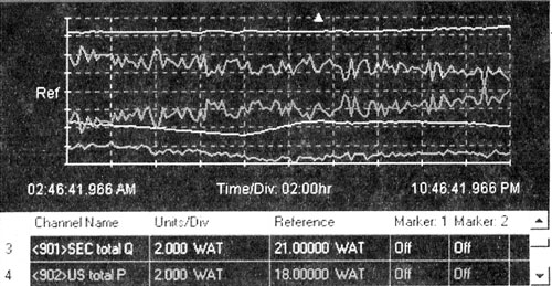
| Figure 3. The excess heat run data for the second
segment. The triangle at the top indicates when the air conditioning was
turned on. The zero for the excess heat trace is the bottom of the graph,
so that whatever is shown is positive, being truly excess heat. It is still
climbing, hypothesized to be caused by the gradual loading of deuterium
into the titanium lattice. The noise of the excess heat is caused by the
noise of the ultrasonic power, which is caused by the sampling rate of the
datalogger (once every 10 minutes) being slightly out of synch with the
ultrasonic power pulses (120 per second). Long-term averaging of this signal
has proven to be accurate. |
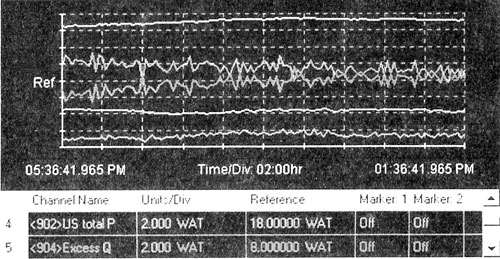
Figure 4. The excess heat run data for the third
and final segment of this data file. The SEC heat at the top of the graph
stabilizes at the same time that the excess heat reaches the maximum of
8.5 watts, average. The ultrasonic power input stabilizes at about 19 watts,
for an excess heat of 40% for the reactor. The excess heat is believed to
be from the fusion of deuterium into helium. |
 |
 |
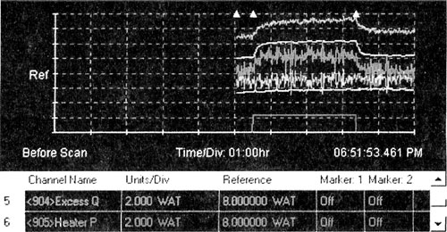
| Figure 5. While the sonofusion reaction
was running, a 2.3 watt pulse of heat was applied inside the SEC. The heat
detected by the SEC rose by 2.3 watts. If the excess heat of 8.5 watts out
of a 19 watt input were an artifact of a drifting calibration, the 2.3 watt
extra input would have measured as a rise of about 3.2 watts. This calibration
check proves that the scaling of the SEC did not change. The sampling rate
was once every minute in this data logger run. The traces are, from top
to bottom, reactor temperature, SEC heat, excess heat, ultrasonic power,
room temperature, and joule heater power. All are spaced vertically for
the convenience of viewing. All of the power traces are 2 watts per vertical
division. |
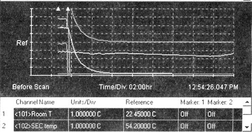
Figure 6. The sonofusion reaction
was terminated shortly after this data logging run was started. The ultrasonic
oscillator was shut off. At this point, the heat remaining in the SEC was
calculated as excess heat, the spike which rose off the graph. Thermal equilibrium
was reached in several hours. The excess heat measurement settled at +0.2
watts, indicating the measuring system did not develop a significant zero
drift. This second post-calibration test, in combination with the first
post-calibration heat pulse input, proves that the instrumentation was operating
accurately. The excess heat measured is legitimate. The traces are identified,
from top to bottom on the left, as SEC temperature (which falls rapidly
off the graph), excess heat (which is zeroed at the reference line and therefore
could show a negative excursion and thus display a system error), SEC heat
(which coasts asymptotically to the bottom trace), ultrasonic power (which
falls rapidly off the graph), room temperature, and circulation fan power
(what the SEC heat line was converging to). The circulation fan and SEC
heat lines are zeroed at the bottom of the graph. At the end of this run,
the +0.2 watt excess heat was the error between the SEC heat and the circulation
fan's DC electrical power input. |
[Top of Page]